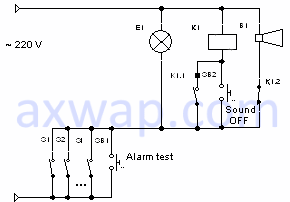
Figure 1. Simple circuit of the light and sound alarm
Here are considered simple schematics of light and sound signaling device for instrumentation and automation.
The general signaling circuit shown in Figure 1 contains the minimum number of switching elements.
Figure 1. Simple circuit of the light and sound alarm
S1...Si – normally open contacts devices relay, closes when the setting values of devices in which the alarm should be triggered.
SB1 – «Alarm test» button. Simulates alarm activation. When pressed, the E1 lamp comes on and a siren sound of B1 is heard.
SB2 – «Sound OFF» button. It is used to mute the alarm sound. Light alarm at the same time continues to run.
K1.1 – normally open contact of relay K1.
K1.2 – normally closed contact of relayе K1.
K1 – an electromagnetic relay / starter, with a working voltage of 220 volts AC on the coil, with one normally closed and one normally open contact.
E1 – incandescent lamp 220 volts - light signaling.
B1 – siren / bell, with operating voltage 220 volts AC - sound alarm.
The operating principle of the alarm
Contacts of the relay of devices S1 ... Si (they can be unlimited quantity), are paralleled with each other and with the button "Alarm test" of the signaling.
When any one of them closes, the "E1" light bulb lights up, and also through the normally closed contact K1.2 of relay K1, the voltage of 220 volts is applied to the siren / buzzer.
If the alarm is on, and you want to mute the sound, by pressing the "Sound OFF" button, the voltage is applied to the relay coil K1. When it is triggered, the siren power circuit is opened (contact K1.2), the sound is turned off. The relay itself is picked up via its contact K1.1.
If the contact of the control device, which triggered the activation of the alarm, opens, then the alarm is turned off, both light and sound. Relay K1 is reset.
Advantages
Simplicity
Disadvantages
When using a bulb and a high-power siren, the relay of devices can pass a high value of current through the switching contacts S1 ... Si, which can lead to their burning and failure. Therefore, when implementing this scheme, it is necessary to ensure that the total current of the bulb and the siren does not exceed the maximum permissible rated current for the output devices (relays) of the devices.
The general signaling circuit shown in Figure 2 according to the principle of operation corresponds to the signaling scheme presented above.
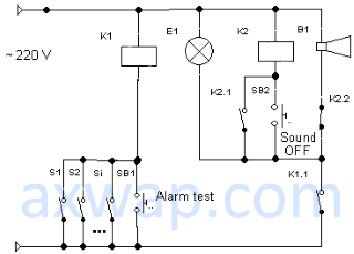
Figure 2. Buffered light and sound alarm system
But here an intermediate buffer relay K1 (~ 220 volts) is added, eliminating the failure of relay contacts of the output devices.
When the relay contact of the device is closed, a relatively small current passes through the relay / starter coil K1, which in most cases does not exceed the maximum permissible rating. At the same time, the closing power contact of this relay / starter can commute a sufficiently large power to connect the light bulb and the siren of the light and sound alarm.
The previous two signaling schemes work in such a way that, when any settings are exceeded, the lamp lights up and the sound is turned on, and when switching to normal mode, both the light and the siren are turned off.
In some cases, it may be necessary to turn on the alarm for a long time, even if the setting of technological parameters is exceeded for a short time.
The diagram of this signaling is shown in Figure 3.
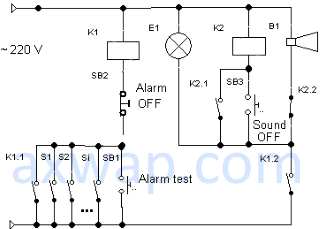
Figure 3. The trigger circuit of the light and sound alarm
The principle of operation is similar to the previous scheme, except that a normally open, self-locking contact K1.1 and a reset button (switch-off) of the SB2 signaling are added to the relay K1.
Even if the devices settings (closing contacts S1 ... Si) are exceeded for a short time, relay K1 will trigger and be locked by contact K1.1.
To reset it to the initial state (turn off the alarm), you can break the power supply circuit of its coil manually with the SB2 button.
The scheme of light and sound signaling using the RTD12 relay is shown in Figure 4.
If the previous circuits are ideally suited for single-channel signaling, when connecting several devices it may not always be convenient to determine which device triggered the alarm. The scheme below works in such a way that when an alarm from an unlimited number of devices triggers a general siren alarm and one or several lights turn on indicating the channel (device) from which the alarm has triggered.

Figure 4. Scheme of light and sound alarm using the RTD12 relay
K1 – alarm testing relay. The coil voltage is 220 V AC.
K2 – relay on / off buzzer. The coil voltage is 220 V AC.
B1 – buzzer / siren 220 V AC.
S1...Si – contacts of the device settings relay (can be unlimited number)
E1...Ei – incandescent bulbs ~ 220 volts, 10 watts.
VD1...VDi - diodes for a voltage of at least 400 volts.
SB1, SB2 – the buttons "alarm test" and "alarm off"
R1 – resistor 2.2 kOm, power not less than 10 W.
The peculiarity of the circuit is that when one of the relay contacts of the output devices is closed, the ~ 220 Volt phase is fed through the corresponding channel lamp to the input of the RTD12 relay, causing its switching on. At the same time, the light is on and the sound alarm is activated.
If the light bulb is faulty, the relay does not turn on, and accordingly neither sound nor light alarms are triggered. To avoid this, you need to periodically check the operation of the alarm, the serviceability of the bulbs. For this purpose, the button SB1 - "alarm test" is designed. When it is pressed, relay K1 is triggered, all serviceable alarm lights come on, and the siren / buzzer is heard.
Turning off the alarm sound by pressing the button SB2 - "sound off".